Vadodara
08048032952
+919408562761

Items tagged with 'locomotive transformer'

6814772a5d263414004dd4a4 Card 2

product image
Transformer Test Set-up

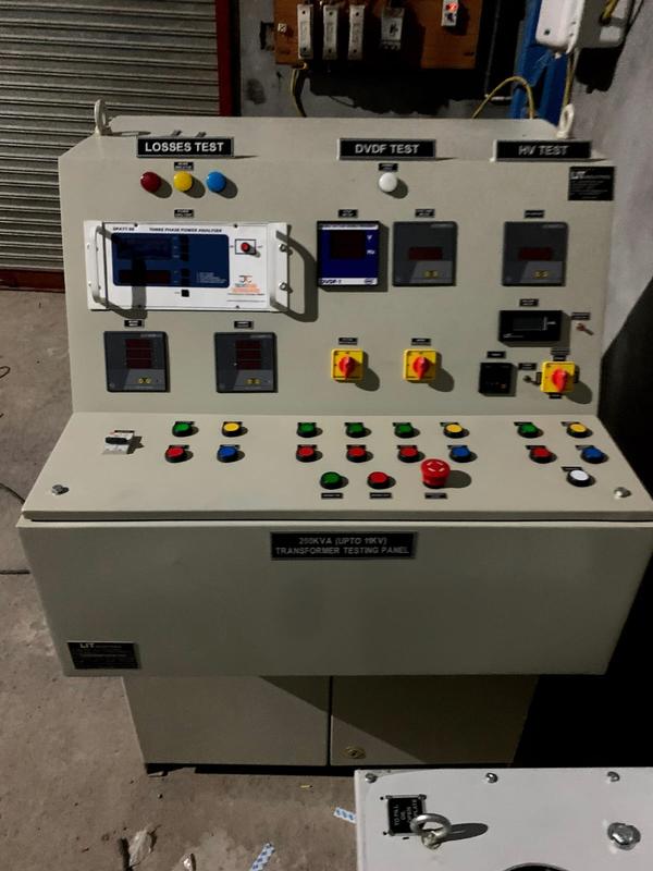
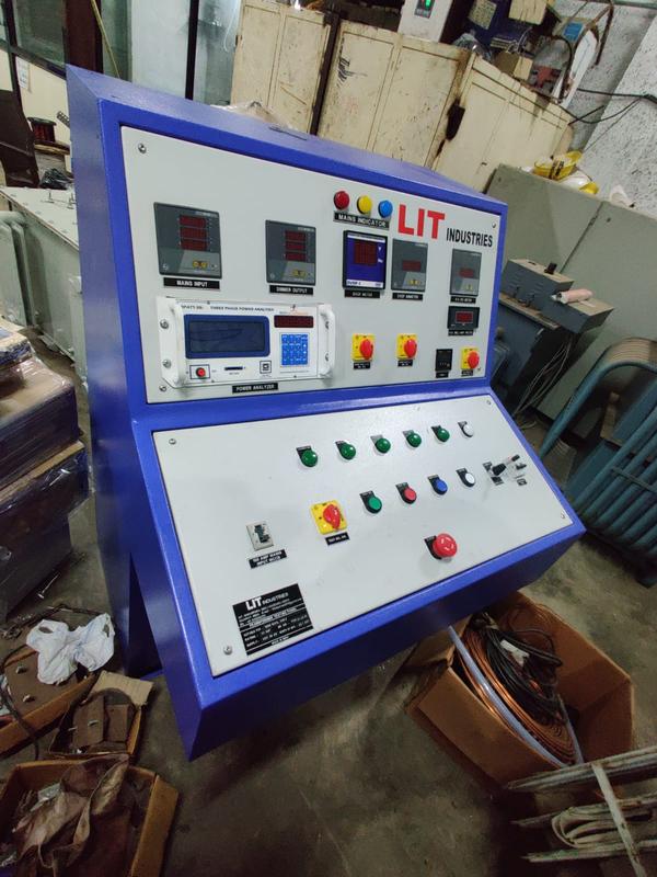
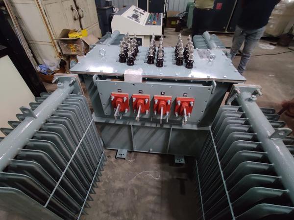
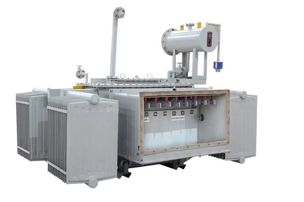
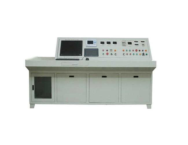
Test bench functionality is vastly improved with the latest tecchnologies like voice commmand operation and an intelligent transformer testing software having a report generation & barcode sticker faciltiy. Test bench consists of fully interfaced test instruments, controlling switchgears, indication lamps, industrial PC, indidcating lamps and various measuring meters.FAT is suitable for testing of all types of transformers including Power Transformer, Distribution Transformer, Furnace Transformer, Dry type, Cast Resin type, Rectifier Transformer, Generator Transformer, and Locomotive Transformer. FAT increases testing productivity significantly by reducing test preparation time, testing process time and report generation time. FAT eliminates the subsequent cable connection time since cabling with instruments is being fixed. Automated data acquisition ensures error free data logging and assists in carrying out statistical/graphical analysis of Test results. Both Auto and Manual modes are available. Software has the facility of multiple user control, manual data entry, database backup facility, printing formulae sheet as per customer requirement.

6814772a5d263414004dd4a4 Card 2

product image
Transformer Test Set-up

LIT Industries make Transformer Testing Panel is designed to simplify the testing of Transformer. Testing panel has many functions, which includes Open Circuit Test, Short Circuit Test, DVDF Test, HV Test. Each test may be conduct using simple Test selections switch. All Controls, Instrument, and connections are panel-mounted for ease of access and viewing.

6814772a5d263414004dd4a4 Card 2

product image
Transformer Test Set-up

Alternately, manual test bench functionally is made more sophisticated with use of a PLC controller. With this test bench discrete indicators, meters selector switches and push buttons are no longer require for this type of testing facility. Automatically test report will be generated through this panel. In addition to the above, customer can see single line diagram of whole power circuit that can be visualize and can be control through computer. The meters of panel is interfaced with computer and PLC.Features: Panel operate through PLC and Software installed in PC All tests can be perform by One Screen The test results are saved in PC as well as in server also if require All the features are given through password protection Auto and Manual Mode available We can measure and test all the tests with less number of connection from panel to testing transformers The size of panel is very compact, so engineer can easily move it from one place to another

6814772a5d263414004dd4a4 Card 2

product image
Transformer Test Set-up

The measurement of the losses in power transformers is an indispensable quality verification process. Due to the fact that normallythe transformer user puts a penalty on the lossesthat occur in the load and no-load modes, thegreatest possible accuracy in measuring thepower losses is of primary economic importance.The TLM system was specially developed for highlyaccurate measurements of power losses intransformers.

6814772a5d263414004dd4a4 Card 2

product image
Transformer Test Set-up

A high-voltage transformer is a device that converts high-voltage AC power to low-voltage AC power or vice versa. High-voltage transformers are mainly used for testing electrical equipment and components under high voltage conditions in laboratories or factories. They can also be used for power transmission and distribution, as well as for special applications such as HVDC, FACTS, and SVC. High-voltage transformers are designed to withstand high voltages and currents without damaging their insulation or core. They are usually oil-immersed, single-phase, core-type transformers with bakelite sheets separating the primary and secondary windings. The cooling system, the bushings, and the voltage regulation of these transformers are also important factors to consider.

6814772a5d263414004dd4a4 Card 2

product image
Transformer

An independent Loss-of-Phase device, to the inherent feature of the inverter, is required if one or more of the following apply: The LDC side of the Interface Transformer is of delta or tee configuration; There is more than one inverter in the DG configuration; It is deemed required by OESC or ESA; There is an Intermediate Transformer present between the Interface Transformer and the inverter(s). HV- Ground point of Intermediate Transformer primary winding.f) Secondary winding resistance measurement.Section: 66 KV Capacitor Voltage Transfor mer Page 4 of 4 SECTION: 66KV ISOLATOR: 1.1 GENERAL:1.1.1 The 66KV isolators shall be outdoor, horizontal centre break type (HCB) complete with terminal connectors suitable for both manual and motor operation.

6814772a5d263414004dd4a4 Card 2

product image
Transformer

A booster transformer is used at end of the transmission line to increase the voltage to the desired value. The main function of the booster transformer is to compensate for the voltage drop in transmission when the transmission line is away from the source. A booster transformer is a device that is used to boost the voltage from the low level to the desired level. Construction of booster transformer The booster transformer is consist of primary and secondary windings. The secondary winding of the booster transformer is connected in series with the transmission line whose voltage shall be controlled and the primary of the booster transformer is supplied from the secondary of the regulating transformer.

6814772a5d263414004dd4a4 Card 2

product image
Transformer

A distribution transformer is the type of transformer that performs the last voltage transformation in a distribution grid. It converts the voltage used in the transmission lines to one suitable for household and commercial use, typically down to 240 volts.[1] These transformers are pole-mounted if the transmission lines run above ground (see figure 1), and they are pad-mounted (see figure 2) if the transmission lines lie underground, as is the case in many suburban areas. The pad-mounted transformer is usually green and visible on the front lawns of many homes. Every utility pole has a grounding wire. There is also a grounding wire that accompanies the two 120 volt hot wires that come from the transformer. These two 120 volt wires are 180° out of phase so that if both electric currents are used, there is a combined voltage of 240 volts. This allows for both 120-volt and 240-volt devices to be powered by the same distribution grid.[1]

6814772a5d263414004dd4a4 Card 2

product image
Transformer

Furnace transformers supply power to electric furnaces of various types like Arc furnace, Induction arc, Submerged arc, Rectifier duty & Ladle furnace transformers.In order withstand repeated short – circuit conditions and high thermal stress and to be protected from operational voltages resulting from the arc process, these transformers are designed after considering demanding conditions. The furnace transformer supplying power to furnace has to handle extremely high value currents in the order of kAmps depending upon furnace ratings.

Still searching for
locomotive transformer?